File download (.blend Blender file): download link
Details about file:
Physical principle:
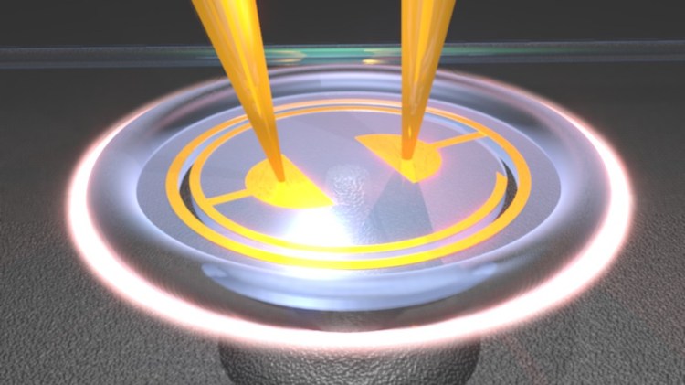
Optomechanical resonators, such as the silica microtoroid pictured above, support both optical resonances which can confine light for long periods of time (here in whispering gallery modes at the periphery of the resonator), and mechanical resonances corresponding to physical deformations of the structure. These devices can be strongly driven with light such that their motion is no longer dominated by chaotic thermal kicks, but instead takes on a large amplitude, spectrally narrow harmonic nature, in a process called regenerative oscillation or phonon lasing. Using this phenomenon, on-chip optomechanical resonators can offer extreme precision in mass and force sensing, but are subject to frequency drifts over time which affect their performance. Through the integration of an electrical interface (integrated gold electrodes in picture above), we demonstrated enhanced stability and noise suppression via inertial injection-locking. We further employ the injection tone to tune the oscillation frequency by more than 2 million times its narrowed linewidth, and show control of the optomechanical gain competition between different mechanical modes of a single resonator. The electrical interface allows enhanced scalability for future applications involving arrays of injection-locked precision sensors. Citation for this work: “Injection locking of an electro-optomechanical device,” C. Bekker, R. Kalra, C. Baker, and W. P. Bowen, Optica, vol. 4, pp. 1196-1204, Sept. 2017.
Rendering details:
The device consists of three main elements: the silica microtoroid resonator, the gold drive electrodes and probe tips, and the coupling fiber taper.
The microtoroid is made of three elements: a silicon pedestal, a central disk and an outer torus representing the reflown outer portion of the resonator. In this work, a slot was etched out in the central disk, in order to increase mechanical compliance of the device. In Blender, such a slot can be made using the Boolean modifier, as shown below:

The glass is rendered by making a material with ‘Raytrace’ transparency. ‘Raytrace’ transparency, unlike ‘Z transparency’, allows for the index of refraction (IOR) of the material to be entered, and produces physically accurate bending of the light rays as they enter and leave the material. This provides a much more realistic glass look, as shown below. (IOR values are for example ~1.44 for silica, and 1.33 for water).


The ‘Fresnel’ and ‘Blend’ settings essentially control the transparency of the material and how much light it reflects/transmits at grazing incidence. The microtoroid pedestal is made from a cone (Shift + a; then m and o) with non-zero top radius (radius 2). For a smoother look, the cone is subdivided in ‘edit mode’ (TAB then ‘loop cut and slide’). Each loop cut circle is made by clicking the left mouse button, choosing its position and clicking LMB again, then scaling the size with the ‘s’ key. This way, the pedestal may have a more accurate shape representative of the etching process.
In our case, the gas etchant used for the release of the disk (Xenon difluoride) creates a roughened, pitted silicon surface, as shown in the image below. This look could be obtained by greatly subdividing the substrate plane, in order for it to contain a large number of vertices, and displacing these in a noisy fashion. Such an approach is however much more resource-intensive due to the large number of vertices in the geometry. A less accurate but quicker and easier way to get the desired rough aspect is through the texture settings. Choosing a noisy texture, and selecting the ‘Geometry’ / ‘normal’ box effectively converts the noisy texture into perturbations of the object’s surface normals (bump mapping), affecting how the light reflects off the object. Note however that this trick only creates the illusion of roughness and does not actually create physical bumps on the surface, so it gives poor results when observing the object with grazing incidence.


The glow of the laser beam confined inside the microresonator is made from a subdivided circle (256 vertices), given the ‘Halo’ material. Since the Halo effect is not visible through materials with ‘Raytrace’ transparency (such as the silica toroid), only the evanescent component of the light field reaching outside the resonator is visible in the rendering.
The electrodes and probe tips are made out of gold. To create a gold look, the material should have a yellow diffuse and specular color, and have an intermediate level of reflectivity. Indeed, too low reflectivity makes the material look like yellow paint, while too high reflectivity makes the object appear colorless, like a perfect mirror.
Compositing/post processing
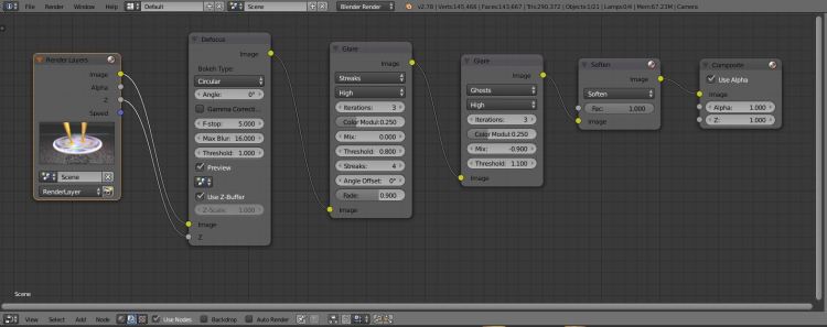
Once the model has finished rendering, the appearance of the image can be improved through post-processing tools integrated in the Blender software. This is accessible through the ‘node editor’, under the ‘compositing’ node tree.The compositing node settings used for this model are shown and detailed below.

Defocus
When looking at a small object up close, the human eye will accommodate by increasing its focal power, i.e. by reducing its focal length. As a consequence light from objects in the background will be over-focussed, with a focal point now positioned in front of the retina. The background behind the object will therefore appear blurry, out-of-focus. Blender images will often appear fake, as they will be sharp everywhere from foreground to background, something that would not occur with the human eye or a camera lens, which have a shallower depth of field. The rendered image can therefore be made to appear more ‘realistic’ in post-processing by emulating this shallower depth of field, using the defocus node (shift+a; Filter; defocus).
This is done by first selecting the focal point of the camera, that is selecting an object in the scene which will be sharp, as shown below left. Next, the ‘defocus node’ will blur objects positioned in front or behind this focal point, with a blurring strength proportional to the distance from the focal point. In order to do this, the defocus node needs to know the depth of the objects in the scene (link the Z terminal, and select ‘use Z-Buffer’ as shown below). The strength of this defocus effect is set by selecting the ‘F-stop’ value in the node. Low f-stop values correspond to a small f-number lens, with shallow depth-of-field (i.e. strong blurring effect), while the max f-stop number (128) corresponds to infinite depth of field and perfect focus everywhere in the scene.


Glare
The Glare compositing node can be used to add common imaging artifacts such as lens flares, ghosts etc to the rendering. These help make scene more realistic, in particular the bright optical field confined inside the resonator. See the blender online manual for more details.
Keywords: Cavity optomechanics, silica microtoroid, Blender, 3D rendering, fiber taper, laser in cavity, gold electrodes, capacitive driving, injection locking, how to make a laser beam in blender, blender for physicists, depth of field, camera focus in blender, blender tutorial.
