
File download (.blend Blender file): download link
Details about file:
Physical principle:
For many applications, the uniformity of this evanescent field, which depends on the smoothness of the tapered section, is important. However, imaging of sub-micron fabricated nanotapers has been restricted to destructive or low-precision techniques. Here we demonstrate an optical scattering-based scanning method that uses a probe nanofibre to locally scatter the evanescent field of a sample nanofibre. The method does not damage the sample nanofibre and is easily implemented using only the same equipment as in a standard fibre-puller setup. We demonstrate subnanometre radial resolution at video rates (0.7 nm in 10 ms) on single mode nanofibres, allowing for a complete high-precision profile to be obtained within minutes of fabrication. The method thus enables non-destructive, fast and precise characterisation of optical nanofibers.
Reference for this work: “Nondestructive Profilometry of Optical Nanofibers,” L. S. Madsen, C. Baker, H. Rubinsztein-Dunlop, and W. P. Bowen, Nano Letters, vol. 16, p. 7333, Nov. 2016.
Rendering details:
The model is fairly simple, with each fiber consisting of two concentric cylinders. (The narrow cylinder on the inside represents the fiber core, while the outer cylinder represents the cladding). The thinned tapered section in the middle of each fiber is made by gradually reducing the cylinder diameter using the ‘Loop cut and slide’ option in ‘Edit mode’. ((TAB then ‘loop cut and slide’).
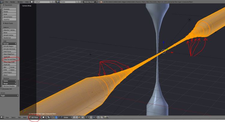
Each loop cut circle is made by clicking the left mouse button, choosing its position and clicking LMB again, then scaling the size with the ‘s’ key). The fiber material has ‘Raytrace’ transparency, which accurately accounts for the bending of light rays due to the materials’ index of refraction (as also discussed in the COEMS model here). The default ‘Depth’ for this material setting is 2. This means that the rendering allows for a maximum of 2 light inter-refractions, making for a unrealistic looking glass. In practice, light may bounce many times inside the fiber on its way from the light source to the camera (observer’s eye). As shown in the figure below, a much nicer result is obtained by setting the ‘Depth’ value to 10.


Using this high setting, particularly in conjunction with the antialiasing set to the max, makes for very long rendering times (>10 minutes on a standard PC). Quick previews can be made by unticking the antialiasing setting, and choosing a low render resolution, as shown below.

Keywords: fiber taper, silica nanotaper, evanescent coupling, silica nanotaper non-destructive profilometry, imaging of silica fiber tapers, lens flare, optical fiber in Blender, 3D rendering of optical nanofiber.
